Fibre Channel over Ethernet (FCoE): Hype vs. Reality

It’s been a bit of a bumpy ride for FCoE, which started out with more promise than it was able to deliver. In theory, the benefits of a single converged LAN/SAN network are fairly easy to see. The problem was, as is often the case with new technology, that most of the theoretical benefit was not available on the initial product release. The idea that storage traffic was no longer confined to expensive SANs, but instead could run on the more commoditized and easier-to-administer IP equipment was intriguing, however, new 10 Gbps Enhanced Ethernet switches were not exactly inexpensive with few products supporting FCoE initially, and those that did, did not play nicely with products from other vendors.

Keeping FCoE “On the Single-Hop”?

The adoption of FCoE to date has been almost exclusively “single-hop”, meaning that FCoE is being deployed to provide connectivity between the server and the Top of Rack switch. Consequently, traffic continues to be broken out one way for IP, and another way for FC. Breaking out the traffic makes sense—by consolidating network adapters and cables, it adds value on the server access side.

A significant portion of FCoE switch ports come from Cisco’s UCS platform, which runs FCoE inside the chassis. In terms of a complete end-to-end FCoE solution, there continues to be very little multi-hop FCoE happening, or ports shipping on storage arrays.

In addition, FCoE connections are more prevalent on blade servers than on stand-alone servers for various reasons.

  • First, blades are used more in a virtualized environment where different types of traffic can travel on the same link.
  • Second, the migration to 10 Gbps has been very slow so far on stand-alone servers; about 80% of these servers are actually still connected with 1 Gbps, which cannot support FCoE.

What portion of FCoE-enabled server ports are actually running storage traffic?

FCoE-enabled ports comprise about a third of total 10 Gbps controller and adapter ports shipped on servers. However, we would like to bring to readers’ attention the wide difference between the portion of 10 Gbps ports that is FCoE-enabled and the portion that is actually running storage traffic. We currently believe less than a third of the FCoE-enabled ports are being used to carry storage traffic. That’s because the FCoE port, in many cases, is provided by default with the server. That’s the case with HP blade servers as well as Cisco’s UCS servers, which together are responsible for around 80% of the FCoE-enabled ports. We believe, however, that in the event that users buy separate adapters they will most likely use that adapter to run storage traffic—but they will need to pay an additional premium for this – about 50% to 100% – for the FCoE license.

The Outlook

That said, whether FCoE-enabled ports are used to carry storage traffic or not, we believe they are being introduced at the expense of some FC adapters. If users deploy a server with an FCoE-enabled port, they most likely will not buy a FC adapter to carry storage traffic. Additionally, as Ethernet speeds reach 40 Gbps, the differential over FC will be too great and FC will be less likely to keep pace.

About the Authors

Casey Quillin is a  Senior Analyst, Storage Area Network & Data Center Appliance Market Research with the Dell’Oro Group

Sameh Boujelbene is a  Senior Analyst, Server and Controller & Adapter Market Research with the Dell’Oro Group

SMB 3.0 – Your Questions Asked and Answered

Last week we had a large and highly-engaged audience at our live Webcast: “SMB 3.0 – New Opportunities for Windows Environments.” We ran out of time answering all the questions during our event so, as promised, here is a recap of all the questions and answers to attendees’ questions. The Webcast is now available on demand at http://snia.org/forums/esf/knowledge/webcasts. You can also download a copy of the presentation slides there.

Q. Have you tested SMB Direct over 40Gb Ethernet or using RDMA?

A. SMB Direct has been demonstrated using 40Gb Ethernet using TCP or RDMA and Infiniband using RDMA.

Q. 100 iops, really?

A. If you look at the bottom right of slide 27 (Performance Test Results) you will see that the vertical axis is IOPs/sec (Normalized). This is a common method for comparing alternative storage access methods on the same storage server. I think we could have done a better job in making this clear by labeling the vertical axis as “IOPs (Normalized).”

Q. How does SMB 3.0 weigh against NFS-4.1 (with pNFS)?

A. That’s a deep question that probably deserves a webcast of its own. SMB 3 doesn’t have anything like pNFS. However many Windows workloads don’t need the sophisticated distributed namespace that pNFS provides. If they do, the namespace is stitched together on the client using mounts and DFS-N.

Q. In the iSCSI ODX case, how does server1 (source) know about the filesystem structure being stored on the LUN (server2) i.e. how does it know how to send the writes over to the LUN?

A. The SMB server (source) does not care about the filesystem structure on the LUN (destination). The token mechanism only loosely couples the two systems. They must agree that the client has permission to do the copy and then they perform the actual copy of a set of blocks. Metadata for the client’s file system representing the copied file on the LUN is part of the client workflow. Client drag/drops file from share to mounted LUN. Client subsystem determines that ODX is available. Client modifies file system metadata on the LUN as part of the copy operation including block maps. ODX is invoked and the servers are just moving blocks.

Q. Can ODX copies be within the same share or only between?

A. There is no restriction to ODX in this respect. The resource and destination of the copy can be on same shares, different shares, or even completely different protocols as illustrated in the presentation.

Q. Does SMB 3 provide API for integration with storage vendor snapshot other MS VSS?

A. Each storage vendor has to support Microsoft Remote VSS protocol, which is part of SMB 3.0 protocol specification. In Windows 2012 or Windows 8 the VSS APIs were extended to support UNC share path.

Q. How does SMB 3 compare to iSCSI rather than FC?

A. Please examine slide 27, which compares SMB 3, FC and iSCSI on the same storage server configuration.

Q. I have a question between SMB and CIFS. I know both are the protocols used for sharing. But why is CIFS adopted by most of the storage vendors? We are using CIFS shares on our NetApps, and I have seen that most of the other storage vendors are also using CIFS on their NAS devices.

A. There has been confusion between the terms “SMB” and “CIFS” ever since CIFS was introduced in the 90s. Fundamentally, the protocol that manages the data transfer between and client and server is SMB. Always has been. IMO CIFS was a marketing term created in response to Sun’s WebNFS. CIFS became popularized with most SMB server vendors calling their product a CIFS server. Usage is slowly changing but if you have a CIFS server it talks SMB.

Q. What is required on the client? Is this a driver with multi-path capability? Is this at the file system level in the client? What is needed in transport layer for the failover?

A. No special software or driver is required on the client side as long as it is running Windows 8 and later operating environment.

Q. Are all these new features cross-platform or is it something only supported by Windows?

A. SMB 3 implementations by different storage vendors will have some set of these features.

Q. Are virtual servers (cloud based) vs. non-virtual transition speeds greatly different?

A. The speed of a transition, i.e. failover is dependent on two steps. The first is the time needed to detect the failure and the second is the time needed to recover from that failure. While both a virtual and a physical server support transition the speed can significantly vary due to different network configurations. See more with next question.

Q. Is there latency as it fails over?

A. Traditionally SMB timeouts were associated with lower level, i.e. TCP timeouts. Client behavior has varied over the years but a rule-of-thumb was detection of a failure in 45 sec. This error would be passed up the stack to the user/application. With SMB 3 there is a new protocol called SMB Witness. A scale-out SMB server will include nodes providing SMB shares as well those providing Witness service. A client connects to SMB and Witness. If the node hosting the SMB share fails, the Witness node will notify the client indicating the new location for the SMB share. This can significantly reduce the time needed for detection. The scale-out SMB server can implement a proprietary mechanism to quickly detect node failure and trigger a Witness notification.

Q. Sync or Async?

A. Whether state movement between server nodes is sync or async depends on vendor implementation. Typically all updated state needs to be committed to stable storage before returning completion to the client.

Q. How fast is this transition with passing state id’s between hosts?

A. The time taken for the transition includes the time needed to detect the failure of Client A and the time needed to re-establish things using Client B. The time taken for both is highly dependent on the nature of the clustered app as well as the supported use case.

Q. We already have FC (using VMware), why drop down to SMB?

A. If you are using VMware with FC, then moving to SMB is not an option. VMware supports the use of NFS for hypervisor storage but not SMB.

Q. What are the top applications on SMB 3.0?

A. Hyper-V, MS-SQL, IIS

Q. How prevalent is true “multiprotocol sharing” taking place with common datasets being simultaneously accessed via SMB and NFS clients?

A. True “multiprotocol sharing” i.e. simultaneous access of a file by NFS & SMB clients is extremely rare. The NFS and SMB locking models don’t lend themselves to that. Sharing of a multiprotocol directory is an important use case. Users may want access to a common area from Linux, OS X and Windows. But this is sequential access by one OS/protocol at a time not all at once.

Q. Do we know growth % split between NFS and SMB?

A. There is no explicit industry tracker for the protocol split and probably not that much point in collecting them either, as the protocols aren’t really in competition. There is affinity among applications, OSes and protocols – MS products tend to SMB (Hyper-V, SQL Server,…), and non-Microsoft to NFS (VMware, Oracle, …). Cloud products at the point of consumption are normally HTTP RESTless protocols.

SUSE Announces NFSv4.1 and pNFS Support

SUSE, founded in 1992, provides an enterprise ready Linux distribution in the form of SLES; the SUSE Linux Enterprise Server. As of late last month (October 22, 2013), SUSE announced that SLES 11 with service pack 3 now supports the Linux client for NFSv4.1 and pNFS client. This major distribution joins RedHat’s RHEL (RedHat Enterprise Linux) 6.4 in supporting enterprise quality Linux distributions with support for files based NFSv4.1 and pNFS.

For the adventurous, block and object pNFS support is available in the upstream kernel. Most regularly maintained distributions based on a Linux 3.1 or better kernel (if not all distributions now – check with the supplier of the distribution if you’re unsure) should provide the files, block and object compliant client directly in the download.

The future of pNFS looks very exciting. We now have a fully pNFS compliant Linux client, and a number of commercial files, blocks and object servers. Remember that although pNFS block and object support is available, currently these distributions support only the pNFS files layout. For those users not needing pNFS with block or objects support and requiring enterprise quality support, SUSE and RedHat are an excellent solution.

Software Defined Networks for SANs?

Previously, I’ve blogged about the VN2VN (virtual node to virtual node) technology coming with the new T11-FC-BB6 specification. In a nutshell, VN2VN enables an “all Ethernet” FCoE network, eliminating the requirement for an expensive Fibre Channel Forwarding (FCF) enabled switch. VN2VN dramatically lowers the barrier of entry for deploying FCoE. Host software is available to support VN2VN, but so far only one major SAN vendor supports VN2VN today. The ecosystem is coming, but are there more immediate alternatives for deploying FCoE without an FCF-enabled switch or VN2VN-enabled target SANs? The answer is that full FC-BB5 FCF services could be provided today using Software Defined Networking (SDN) in conjunction with standard DCB-enabled switches by essentially implementing those services in host-based software running in a virtual machine on the network. This would be an alternative “all Ethernet” storage network supporting Fibre Channel protocols. Just such an approach was presented at SNIA’s Storage Developers Conference 2013 in a presentation entitled, “Software-Defined Network Technology and the Future of Storage,” Stuart Berman, Chief Executive Officer, Jeda Networks. (Note, of course neither approach is relevant to SAN networks using Fibre Channel HBAs, cables, and switches.)

Interest in SDN is spreading like wildfire. Several pioneering companies have released solutions for at least parts of the SDN puzzle, but kerosene hit the wildfire with the $1B acquisition of Nicira by VMware. Now a flood of companies are pursuing an SDN approach to everything from wide area networks to firewalls to wireless networks. Applying SDN technology to storage, or more specifically to Storage Area Networks, is an interesting next step. See Jason Blosil’s blog below, “Ethernet is the right fit for the Software Defined Data Center.”

To review, an SDN abstracts the network switch control plane from the physical hardware. This abstraction is implemented by a software controller, which can be a virtual appliance or virtual machine hosted in a virtualized environment, e.g., a VMware ESXi host. The benefits are many; the abstraction is often behaviorally consistent with the network being virtualized but simpler to manipulate and manage for a user. The SDN controller can automate the numerous configuration steps needed to set up a network, lowering the amount of touch points required by a network engineer. The SDN controller is also network speed agnostic, i.e., it can operate over a 10Gbps Ethernet fabric and seamlessly transition to operate over a 100Gbps Ethernet fabric. And finally, the SDN controller can be given an unlimited amount of CPU and memory resources in the host virtual server, scaling to a much greater magnitude compared to the control planes in switches that are powered by relatively low powered processors.

So why would you apply SDN to a SAN? One reason is SSD technology; storage arrays based on SSDs move the bandwidth bottleneck for the first time in recent memory into the network. An SSD array can load several 10Gbps links, overwhelming many 10G Ethernet fabrics. Applying a Storage SDN to an Ethernet fabric and removing the tight coupling of speed of the switch with the storage control plane will accelerate adoption of higher speed Ethernet fabrics. This will in turn move the network bandwidth bottleneck back into the storage array, where it belongs.

Another reason to apply SDN to Storage Networks is to help move certain application workloads into the Cloud. As compute resources increase in speed and consolidate, workloads require deterministic bandwidth, IOPS and/or resiliency metrics which have not been well served by Cloud infrastructures. Storage SDNs would apply enterprise level SAN best practices to the Cloud, enabling the migration of some applications which would increase the revenue opportunities of the Cloud providers. The ability to provide a highly resilient, high performance, SLA-capable Cloud service is a large market opportunity that is not cost available/realizable with today’s technologies.

So how can SDN technology be applied to the SAN? The most viable candidate would be to leverage a Fibre Channel over Ethernet (FCoE) network. An FCoE network already converges a high performance SAN with the Ethernet LAN. FCoE is a lightweight and efficient protocol that implements flow control in the switch hardware, as long as the switch supports Data Center Bridging (DCB). There are plenty of standard “physical” DCB-enabled Ethernet switches to choose from, so a Storage SDN would give the network engineer freedom of choice. An FCoE based SDN would create a single unified, converged and abstracted SAN fabric. To create this Storage SDN you would need to extract and abstract the FCoE control plane from the switch removing any dependency of a physical FCF. This would include the critical global SAN services such as the Name Server table, the Zoning table and State Change Notification. Containing the global SAN services, the Storage SDN would also have to communicate with initiators and targets, something an SDN controller does not do. Since FCoE is a network-centric technology, i.e., configuration is performed from the network, a Storage SDN can automate large SAN’s from a single appliance. The Storage SDN should be able to create deterministic, end-to-end Ethernet fabric paths due to the global view of the network that an SDN controller typically has.

A Storage SDN would also be network speed agnostic, since Ethernet switches already support 10Gbps, 40Gbps, and 100Gbps this would enable extremely fast SANs not currently attainable. Imagine the workloads, applications and consolidation of physical infrastructure possible with a 100Gbps Storage SDN SAN all controlled by a software FCoE virtual server connecting thousands of servers with terabytes of SSD storage? SDN technology is bursting with solutions around LAN traffic; now we need to tie in the SAN and keep it as non-proprietary to the hardware as possible.

Q&A Summary from the SNIA-ESF Webcast – “How VN2VN Will Help Accelerate Adoption of FCoE”

Our VN2VN Webcast last week was extremely well received. The audience was big and highly engaged. Here is a summary of the questions attendees asked and answers from my colleague, Joe White, and me. If you missed the Webcast, it’s now available on demand.

Question #1:

We are an extremely large FC shop with well over 50K native FC ports. We are looking to bridge this to the FCoE environment for the future. What does VN2VN buy the larger company? Seems like SMB is a much better target for this.

Answer #1: It’s true that for large port count SAN deployments VN2VN is not the best choice but the split is not strictly along the SMB/large enterprise lines. Many enterprises have multiple smaller special purpose SANs or satellite sites with small SANs and VN2VN can be a good choice for those parts of a large enterprise. Also, VN2VN can be used in conjunction with VN2VF to provide high-performance local storage, as we described in the webcast.

Question #2: Are there products available today that incorporate VN2VN in switches and storage targets?

Answer #2: Yes. A major storage vendor announced support for VN2VN at Interop Las Vegas 2013. As for switches, any switch supporting Data Center Bridging (DCB) will work. Most, if not all, new datacenter switches support DCB today. Recommended also is support in the switch for FIP Snooping, which is also available today.

Question #3: If we have an iSNS kind of service for VN2VN, do you think VN2VN can scale beyond the current anticipated limit?

Answer #3: That is certainly possible. This sort of central service does not exist today for VN2VN and is not part of the T11 specifications so we are talking in principle here. If you follow SDN (Software Defined Networking) ideas and thinking then having each endpoint configured through interaction with a central service would allow for very large potential scaling. Now the size and bandwidth of the L2 (local Ethernet) domain may restrict you, but fabric and distributed switch implementations with large flat L2 can remove that limitation as well.

Question #4: Since VN2VN uses different FIP messages to do login, a unique FSB implementation must be provided to install ACLs. Have any switch vendors announced support for a VN2VN FSB?

Answer #4: Yes, VN2VN FIP Snooping bridges will exist. It only requires a small addition to the filet/ACL rules on the FSB Ethernet switch to cover VN2VN. Small software changes are needed to cover the slightly different information, but the same logic and interfaces within the switch can be used, and the way the ACLs are programmed are the same.

Question #5: Broadcasts are a classic limiter in Layer 2 Ethernet scalability. VN2VN control is very broadcast intensive, on the default or control plane VLAN. What is the scale of a data center (or at least data center fault containment domain) in which VN2VN would be reliably usable, even assuming an arbitrarily large number of data plane VLANs? Is there a way to isolate the control plane broadcast traffic on a hierarchy of VLANs as well?

Answer #5: VLANs are an integral part of VN2VN within the T11 FC-BB-6 specification. You can configure the endpoints (servers and storage) to do all discovery on a particular VLAN or set of VLANs. You can use VLAN discovery for some endpoints (mostly envisioned as servers) to learn the VLANs on which to do discovery from other endpoints (mostly envisioned as storage). The use of VLANs in this manner will contain the FIP broadcasts to the FCoE dedicated VLANs. VN2VN is envisioned initially as enabling small to medium SANs of about a couple hundred ports although in principle the addressing combined with login controls allows for much larger scaling.

Question #6: Please explain difference between VN2VN and VN2VF

Answer #6: The currently deployed version of FCoE, T11 FC-BB-5, requires that every endpoint, or Enode in FC-speak, connect with the “fabric,” a Fibre Channel Forwarder (FCF) more specifically. That’s VN2VF. What FC-BB-6 adds is the capability for an endpoint to connect directly to other endpoints without an FCF between them. That’s VN2VN.

Question #7: In the context of VN2VN, do you think it places a stronger demand for QCN to be implemented by storage devices now that they are directly (logically) connected end-to-end?

Answer #7: The QCN story is the same for VN2VN, VN2VF, I/O consolidation using an NPIV FCoE-FC gateway, and even high-rate iSCSI. Once the discovery completes and sessions (FLOGI + PLOGI/PRLI) are setup, we are dealing with the inherent traffic pattern of the applications and storage.

Question #8: Your analogy that VN2VN is like private loop is interesting. But it does make VN2VN sound like a backward step – people stopped deploying AL tech years ago (for good reasons of scalability etc.). So isn’t this just a way for vendors to save development effort on writing a full FCF for FCoE switches?

Answer #8: This is a logical private loop with a lossless packet switched network for connectivity. The biggest issue in the past with private or public loop was sharing a single fiber across many devices. The bandwidth demands and latency demands were just too intense for loop to keep up. The idea of many devices addressed in a local manner was actually fairly attractive to some deployments.

Question #9: What is the sweet spot for VN2VN deployment, considering iSCSI allows direct initiator and target connections, and most networks are IP-enabled?

Answer #9: The sweet spot if VN2VN FCoE is SMB or dedicated SAN deployments where FC-like flow control and data flow are needed for up to a couple hundred ports. You could implement using iSCSI with PFC flow control but if TCP/IP is not needed due to PFC lossless priorities — why pay the TCP/IP processing overhead? In addition the FC encapsulation/serializaition and FC exchange protocols and models are preserved if this is important or useful to the applications. The configuration and operations of a local SAN using the two models is comparable.

Question #10: Has iSCSI become irrelevant?

Answer #10: Not at all. iSCSI serves a slightly different purpose from FCoE (including VN2VN). iSCSI allows connection across any IP network, and due to TCP/IP you have an end-to-end lossless in-order delivery of data. The drawback is that for high loss rates, burst drops, heavy congestion the TCP/IP performance will suffer due to congestion avoidance and retransmission timeouts (‘slow starts’). So the choice really depends on the data flow characteristics you are looking for and there is not a one size fits all answer.

Question #11: Where can I watch this Webcast?

Answer #11: The Webcast is available on demand on the SNIA website here.

Question #12: Can I get a copy of these slides?

Answer #12: Yes, the slides are available on the SNIA website here.

Ethernet is the right fit for the Software Defined Data Center

“Software Defined” is a  label being used to define advances in  network and storage virtualization and promises to greatly improve infrastructure management and accelerate business agility. Network virtualization itself isn’t a new concept and has been around in various forms for some time (think vLANs). But, the commercialization of server virtualization seems to have paved the path to extend virtualization throughout the data center infrastructure, making the data center an IT environment delivering dynamic and even self-deployed services. The networking stack has been getting most of the recent buzz and I’ll focus on that portion of the infrastructure here.

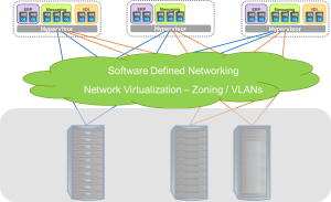
VirtualizationChangesWhat is driving this trend in data networking? As I mentioned, server virtualization has a lot to do with the new trend. Virtualizing applications makes a lot of things better, and makes some things more complicated. Server virtualization enables you to achieve much higher application density in your data center. Instead of a one-to-one relationship between the application and server, you can host tens of applications on the same physical  server. This is great news for data centers that run into space limitations or for businesses looking for greater efficiency out of their existing hardware.

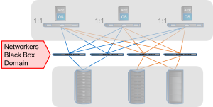
YesteryearThe challenge, however, is that these applications aren’t stationary. They can move from one physical server to another. And this mobility can add complications for the networking guys. Networks must be aware of virtual machines in ways that they don’t have to be aware of physical servers. For network admins of yesteryear, their domain was a black box of “innies” and “outies”. Gone are the days of “set it and forget it” in terms of networking devices. Or is it?

Software defined networks (aka SDN) promise to greatly simplify the network environment. By decoupling the control plane from the data plane, SDN allows administrators to treat a collection of networking devices as a single entity and can then use policies to configure and deploy networking resources more dynamically. Additionally, moving to a software defined infrastructure means that you can move control and management of physical devices to different applications within the infrastructure, which give you flexibility to launch and deploy virtual infrastructures in a more agile way.

network virtualizationSoftware defined networks aren’t limited to a specific physical transport. The theory, and I believe implementation, will be universal in concept. However, the more that hardware can be deployed in a consistent manner, the greater flexibility for the enterprise. As server virtualization becomes the norm, servers hosting applications with mixed protocol needs (block and file) will be more common. In this scenario, Ethernet networks offer advantages, especially as software defined networks come to play. Following is a list of some of the benefits of Ethernet in a software defined network environment.

Ubiquitous

Ethernet is a very familiar technology and is present in almost every compute and mobile device in an enterprise. From IP telephony to mobile devices, Ethernet is a networking standard commonly deployed and as a result, is very cost effective. The number of devices and engineering resources focused on Ethernet drives the economics in favor of Ethernet.

Compatibility

Ethernet has been around for so long and has proven to “just work.” Interoperability is really a non-issue and this extends to inter-vendor interoperability. Some other networking technologies require same vendor components throughout the data path. Not the case with Ethernet. With the rare exception, you can mix and match switch and adapter devices within the same infrastructure. Obviously, best practices would suggest that at least a single vendor within the switch infrastructure would simplify the environment with a common set of management tools, features,  and support plans. But, that might change with advances in SDN.

Highly Scalable

Ethernet is massively scalable. The use of routing technology allows for broad geographic networks. The recent adoption of IPv6 extends IP addressing way beyond what is conceivable at this point in time. As we enter the “internet of things” period in IT history, we will not lack for network scale. At least, in theory.

Overlay Networks

Overlay Networksallow you to extend L2 networks beyond traditional geographic boundaries. Two proposed standards are under review  by the Internet Engineering Task Force (IETF). These include Virtual eXtensible Local Area Networks (VXLAN) from VMware and Network Virtualization using Generic Routing Encapsulation (NVGRE) from Microsoft. Overlay networks combine L2  and L3 technologies to extend the L2 network beyond traditional geographic boundaries, as with hybrid clouds. You can think of overlay networks as essentially a generalization of a vLAN. Unlike with routing, overlay networks permit you to retain visibility and accessibility of your L2 network across larger geographies.

Unified Protocol Access

Ethernet has the ability to support mixed storage protocols, including iSCSI, FCoE, NFS, and CIFS/SMB. Support for mixed or unified environments can be more efficiently deployed using 10 Gigabit Ethernet (10GbE) and Data Center Bridging (required for FCoE traffic) as IP and FCoE traffic can share the same ports. 10GbE simplifies network deployment as the data center can be wired once and protocols can be reconfigured with software, rather than hardware changes.

Virtualization

Ethernet does very well in virtualized environments. IP address can easily be abstracted from physical ports to facilitate port mobility. As a result, networks built on an Ethernet infrastructure leveraging network virtualization can benefit from increased flexibility and uptime as hardware can be serviced or upgraded while applications are online.

Roadmap

For years, Ethernet has increased performance, but the transition from Gigabit Ethernet to 10 Gigabit Ethernet was a slow one. Delays in connector standards complicated matters. But, those days are over and the roadmap remains robust and product advances are accelerating. We are starting to see 40GbE devices on the market today, and will see 100GbE devices in the near future. As more and more data traffic is consolidated onto a shared infrastructure, these performance increases will provide the headroom for more efficient infrastructure deployments.

Some of the benefits listed above can be found with other networking technologies. But, Ethernet technology offers a unique combination of technology and economic value across a broad ecosystem of vendors that make it an ideal infrastructure for next generation data centers. And as these data centers are designed more and more around application services, software will be the lead conversation. To enable the vision of a software defined infrastructure, there is no better network technology than Ethernet.

pNFS and Future NFSv4.2 Features

In this third and final blog post on NFS (see previous blog posts Why NFSv4.1 and pNFS are Better than NFSv3 Could Ever Be and The Advantages of NFSv4.1) I’ll cover pNFS (parallel NFS), an optional feature of NFSv4.1 that improves the bandwidth available for NFS protocol access, and some of the proposed features of NFSv4.2 – some of which are already implemented in commercially available servers, but will be standardized with the ratification of NFSv4.2 (for details, see the IETF NFSv4.2 draft documents).

Finally, I’ll point out where you can get NFSv4.1 clients with support for pNFS today.

Parallel NFS (pNFS) and Layouts

Parallel NFS (pNFS) represents a major step forward in the development of NFS. Ratified in January 2010 and described in RFC-5661, pNFS depends on the NFS client understanding how a clustered filesystem stripes and manages data. It’s not an attribute of the data, but an arrangement between the server and the client, so data can still be accessed via non-pNFS and other file access protocols.   pNFS benefits workloads with many small files, or very large files, especially those run on compute clusters requiring simultaneous, parallel access to data.
NFS 3 image 1

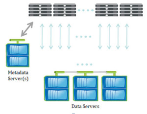
Clients request information about data layout from a Metadata Server (MDS), and get returned layouts that describe the location of the data. (Although often shown as separate, the MDS may or may not be standalone nodes in the storage system depending on a particular storage vendor’s hardware architecture.) The data may be on many data servers, and is accessed directly by the client over multiple paths. Layouts can be recalled by the server, as in the case for delegations, if there are multiple conflicting client requests.  

By allowing the aggregation of bandwidth, pNFS relieves performance issues that are associated with point-to-point connections. With pNFS, clients access data servers directly and in parallel, ensuring that no single storage node is a bottleneck. pNFS also ensures that data can be better load balanced to meet the needs of the client.

The pNFS specification also accommodates support for multiple layouts, defining the protocol used between clients and data servers. Currently, three layouts are specified; files as supported by NFSv4, objects based on the Object-based Storage Device Commands (OSD) standard (INCITS T10) approved in 2004, and block layouts (either FC or iSCSI access). The layout choice in any given architecture is expected to make a difference in performance and functionality. For example, pNFS object based implementations may perform RAID parity calculations in software on the client, to allow RAID performance to scale with the number of clients and to ensure end-to-end data integrity across the network to the data servers.

So although pNFS is new to the NFS standard, the experience of users with proprietary precursor protocols to pNFS shows that high bandwidth access to data with pNFS will be of considerable benefit.

Potential performance of pNFS is definitely superior to that of NFSv3 for similar configurations of storage, network and server. The management is definitely easier, as NFSv3 automounter maps and hand-created load balancing schemes are eliminated; and by providing a standardized interface, pNFS ensures fewer issues in supporting multi-vendor NFS server environments.

Some Proposed NFSv4.2 features

NFSv4.2 promises many features that end-users have been requesting, and that makes NFS more relevant as not only an “every day” protocol, but one that has application beyond the data center. As the requirements document for NFSv4.2 puts it, there are requirements for:  

  • High efficiency and utilization of resources such as, capacity, network bandwidth, and processors.
  • Solid state flash storage which promises faster throughput and lower latency than magnetic disk drives and lower cost than dynamic random access memory.

Server Side Copy

Server-Side Copy (SSC) removes one leg of a copy operation. Instead of reading entire files or even directories of files from one server through the client, and then writing them out to another, SSC permits the destination server to communicate directly to the source server without client involvement, and removes the limitations on server to client bandwidth and the possible congestion it may cause.

Application Data Blocks (ADB)

ADB allows definition of the format of a file; for example, a VM image or a database. This feature will allow initialization of data stores; a single operation from the client can create a 300GB database or a VM image on the server.

Guaranteed Space Reservation & Hole Punching

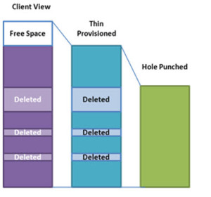
As storage demands continue to increase, various efficiency techniques can be employed to give the appearance of a large virtual pool of storage on a much smaller storage system.   Thin provisioning, (where space appears available and reserved, but is not committed) is commonplace, but often problematic to manage in fast growing environments. The guaranteed space reservation feature in NFSv4.2 will ensure that, regardless of the thin provisioning policies, individual files will always have space available for their maximum extent.
NFS 3 image 2

While such guarantees are a reassurance for the end-user, they don’t help the storage administrator in his or her desire to fully utilize all his available storage. In support of better storage efficiencies, NFSv4.2 will introduce support for sparse files. Commonly called “hole punching”, deleted and unused parts of files are returned to the storage system’s free space pool.

Obtaining Servers and Clients

With this background on the features of NFS, there is considerable interest in the end-user community for NFSv4.1 support from both servers and clients. Many Network Attached Storage (NAS) vendors now support NFSv4, and in the last 12 months, there has been a flurry of activity and many developments in server support of NFSv4.1 and pNFS.

For NFS server vendors, there are NFSv4.1 and files based, block based and object based implementations of pNFS available; refer to the vendor websites, where you will get the latest up-to-date information.

On the client side, there is RedHat Enterprise Linux 6.4 that includes full support for NFSv4.1 and pNFS (see www.redhat.com), Novell SUSE Linux Enterprise Server 11 SP2 with NFSv4.1 and pNFS based on the 3.0 Linux kernel (see www.suse.com), and Fedora available at fedoraproject.org.

Conclusion          

NFSv4.1 includes features intended to enable its use in global wide area networks (WANs).   These advantages include:

  • Firewall-friendly single port operations
  • Advanced and aggressive cache management features
  • Internationalization support
  • Replication and migration facilities
  • Optional cryptography quality security, with access control facilities that are compatible across UNIX ® and Windows ®
  • Support for parallelism and data striping

The goal for NFSv4.1 and beyond is to define how you get to storage, not what your storage looks like. That has meant inevitable changes. Unlike earlier versions of NFS, the NFSv4 protocol integrates file locking, strong security, operation coalescing, and delegation capabilities to enhance client performance for data sharing applications on high-bandwidth networks.

NFSv4.1 servers and clients provide even more functionality such as wide striping of data to enhance performance.   NFSv4.2 and beyond promise further enhancements to the standard that increase its applicability to today’s application requirements. It is due to be ratified in August 2012, and we can expect to see server and client implementations that provide NFSv4.2 features soon after this; in some cases, the features are already being shipped now as vendor specific enhancements.  

With careful planning, migration to NFSv4.1 (and NFSv4.2 when it becomes generally available) from prior versions can be accomplished without modification to applications or the supporting operational infrastructure, for a wide range of applications; home directories, HPC storage servers, backup jobs and a variety of other applications.


FOOTNOTE: Parts of this blog were originally published in Usenix ;login: February 2012 under the title The Background to NFSv4.1. Used with permission.

Update: Want to learn more about NFS? Check out these SNIA ESF webcasts:
 

10 Gigabit Ethernet – 2H12 Results and 2013 Outlook

Seamus Crehan, President, Crehan Research Inc.

2H12 results

2012 turned out be another very strong growth year for 10 Gigabit Ethernet (10GbE), with the data center switch market and the server-class adapter and LAN-on-Motherboard (LOM) market both growing more than 50%.   Broad long-term trends such as virtualization, convergence, data center network traffic growth, cloud deployments, and price declines were helped further by more specific demand drivers, many of which materialized in the latter half of 2012. These included the adoption of Romley servers, expanded 10GBASE-T product offerings for both switches and servers, 10GbE LOM solutions for volume rack servers (which drive the majority of server shipments), and the public cloud’s migration to 10GbE for mainstream server networking access. (The SNIA Ethernet Storage Forum wrote about many of these in its July 2012 whitepaper titled 10GbE Comes of Age).

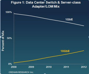
However, despite another stellar growth year, 10GbE still remained a minority of the overall data center and server shipment mix (see Figure 1).    

Crehan figure 1

Furthermore, its adoption hit some turbulence in the latter half of 2012, mostly related to the initial high prices and the learning curve associated with the new Modular LOM form-factor, resulting in some inventory issues.   Another drag on 2H12 10GbE growth was the lack of comprehensive 10GBASE-T offerings from many market participants. Although we saw a very significant step up in 10GBASE-T shipments in 2012, limited product offerings throughout much of 2012 capped its adoption at under less than 10% of total 10GbE shipments.

But these 2H12 issues were more than offset by 10GbE entering its next major stage of volume server adoption during this time period.   Crehan Research reported a near-50% increase in 2H12 10GbE results as many public cloud, Web 2.0, and massively scalable data center companies deployed 10GbE servers and server-access data center switches. We believe this is the second of three major stages of mainstream 10GbE server adoption, the first of which was driven by blade servers. The third will be driven by the upgrade of the traditional enterprise segment’s large installed base of 1GbE rack and tower server ports to 10GbE.

2013 expectations

As we move through 2013, Crehan Research expects the following factors to have positive impacts on the 10GbE market, driving it closer to becoming the majority data center networking interconnect:

Better pricing and understanding of Modular LOMs.   Initial pricing on 10GbE Modular LOMs has been relatively high, contributing to slower adoption and inventory issues.  In the past, end customers were given the higher-speed LOM for free for example, during the 1GbE and blade-server 10GbE transitions.   The Modular LOM is a new product form-factor, and it takes time for buyers and sellers to get comfortable with and fully understand it. During 2013, we should see lower pricing for this class of product, driving a higher server attach rate.

Comprehensive 10GBASE-T product offerings. 2013 should finally bring complete 10GBASE-T product offerings from the major server and switch OEMs, helping drive stronger 10GBASE-T adoption and growth. More specifically, we should see more 10GBASE-T LOMs in addition to top-of-rack and end-of-row data center switches. Furthermore, we expect many of these products to be attractively priced, in order to entice the large installed base of 1GBASE-T customers to upgrade to 10GbE.

Higher-speed uplink, aggregation, and core data center switches. Servers and server-access switches likely won’t see volume deployments to 10GbE without robust and cost-effective higher-speed uplink, aggregation, and core networking options. These have now begun to arrive with 40GbE, and we are starting to see a strong ramp for this technology. Crehan Research expects 2013 to bring the advent of many 40GbE data center switches, and foresees all of the major switch vendors rolling out offerings in 2013. In contrast with the early days of 10GbE, 40GbE prices are already close to parity on a bandwidth basis with 10GbE and have settled on a single interface form factor (QSFP), which should propel 40GbE data center switches to a much stronger start than that seen by 10GbE data center switches.

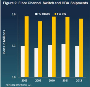
Continued traction of 10GbE for storage applications. We expect that 2013 will see a continuation of the broader adoption of 10GbE as a storage protocol, in both the public cloud and traditional enterprise segments.  Although Fibre Channel remains a very important data center storage networking technology, Fibre Channel switch and Host Bus Adapter (HBA) shipments each declined slightly in 2012 and have seen flat compound annual growth rates over the past four years (see Figure 2). We expect this gradual Fibre Channel decline to continue in 2013 as more customers run Ethernet-based protocols such as NAS, iSCSI and FCoE, especially over 10GbE, for their storage needs and deployments.

Crehan figure 2

Resolving the Confusion around DCB (I Hope)

Storage traffic running over Ethernet-based networks has been around for as long as we have had Ethernet-based networks.   Of course sometimes it is technically not accurate to think of the protocols as fundamentally Ethernet protocols – whilst FCoE, by definition, only runs on Ethernet, iSCSI, SMB, and NFS,  they are, in reality, IP-based storage protocols and whilst most commonly run on Ethernet, could run on any network that supports IP.   That notwithstanding, it is increasingly important to understand the real nature of Ethernet, and in particular, the nature of the new enhancements that we put under the umbrella of Data Center Bridging (DCB).

Although there is a great deal of information around DCB, there is also a lot of confusion where even the best articles miss describing a number of its elements.   As such, with 10GbE ramping now is a good time to try to clarify the reality of what DCB does and does not do.

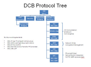
Perhaps the first and most important point is that DCB is, in reality, a task group in IEEE responsible for the development enhancements to the 802.1 bridge specifications that apply specifically to Ethernet Switching (or as IEEE say Bridging) in the datacenter.   As such, DCB is not in itself a standard nor is the DCB group solely involved in those standards that apply to I/O and network convergence.   The mots recent work of this task group falls into two distinct areas both of which apply to the datacenter ­ one is the now completed standards around network and I/O convergence (802.1Qau,Qaz, Qbb) but the other are those standards that address the impact of server virtualization technology (802.1Qbg, BR, and the now withdrawn Qbh).  

Protocol Tree

Also critical to understand, so that we do not overstate either the limitations of traditional Ethernet nor the advantages of the new standards around I/O and network convergence, is that these new standards build on top of many well understood, well used mature capabilities that already exist within the IEEE Ethernet standards set.   Indeed IMHO, the most important element of this is that the DCB Convergence standards are building on top of the 802.1p capability to specify eight different classes of service through a 3-bit PCP field in the 802.1Q header ­ the VLAN header.   Or to say that in English ­ Ethernet has for some considerable time had the ability to separate traffic into 8 separate categories to ensure that those different categories got different treatment – or more bluntly the fundamentals of I/O and network convergence are nothing new to Ethernet.   Not only that, but the VLAN identification itself can be used to apply QoS on different sets of traffic, as does the fact that we can usually identify different traffic types by the Ethertype or IP socket.

So what is all the fuss about? As much as there were some good convergence capabilities, it was recognized that these could be further enhanced.

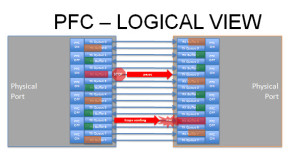
802.1Qbb or Priority-based Flow Control (PFC), far from adding into Ethernet a non-existent capability for lossless, simply takes the existing capability for lossless ­ 802.3X ­ and enhances it.   802.3X, when deployed with both RX and TX pause, can give lossless Ethernet as both recognized by many in the iSCSI community as well as by the FCoE specifications.   However, the pause mechanisms apply at the port level, which means giving one traffic class lossless causes blocking of other traffic classes.   All 802.1Qbb does, along with 802.3bd, is allow the pause mechanisms to be applied individually to specific priorities or traffic classes ­ aka pause FCoE or iSCSI or RoCE whilst allowing other traffic to flow.  

PFC

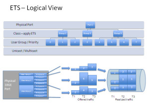
802.1Qaz or ETS (let’s ignore that DCBX is also part of this document and discussed in another SNIA-ESF blog) is not bandwidth allocation to your individual priorities, rather it is the ability to create a group of priorities and apply bandwidth rules to that group.   In English, it adds a new tier to your QoS schedulers so you can now apply bandwidth rules to port, priority or class group, individual priority, and VLAN.   The standard suggests a practice of at least three groups, one for best effort traffic classes, one for PFC-lossless classes, and one for strict priority ­ though it does allow more groups.  

ETS logical view

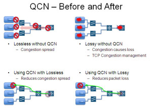
Last but not least, 802.1Qau or QCN is not a mechanism to provide lossless capabilities.   Where pause and PFC are point-to-point flow control mechanisms QCN allows flow control to be applied by a message from the congestion point all the way back to the source.   Being Ethernet level mechanisms it is of course across multiple hops within a layer 2 domain and so cannot cross either IP routing or FCF FCoE-based forwarding.   If QCN is applied to a non PFC priority, then it would most likely reduce drop by telling the source device to slow down rather than having frames be dropped and allowing the TCP congestion window to trigger slowing down at the TCP level.   If QCN is applied to a PFC priority, then it could reduce back propagation of PFC pause and so congestion propagation within that priority.  

QCN

Although not part of the standards for DCB-based convergence, but mentioned in the standards, devices that implement DCB typically have some form of buffer carving or partitioning such that the different traffic classes are not just on different priorities or classes as they flow through the network, but are being queued in and utilizing separate buffer queues.   This is important as the separated queuing and buffer allocation is another aspect of how fate sharing is limited or avoided between the different traffic classes.   It also makes conversations around microbursts, burst absorption, and latency bubbles all far more complex than before when there was less or no buffer separation.

It is important to remember that what we are describing here are the layer 2 Ethernet mechanisms around I/O and network convergence, QoS, flow control.   These are not the only tools available (or in operation) and any datacenter design needs to fully consider what is happening at every level of the network and server stack ­ including, but not limited to, the TCP/IP layer, SCSI layer, and indeed application layer.   The interactions between the layers are often very interesting ­ but that is perhaps the subject for another blog.

In summary, with the set of enhanced convergence protocols now fully standardized and fairly commonly available on many platforms, along with the many capabilities that exist within Ethernet, and the increasing deployment of networks with 10GbE or above, more organizations are benefiting from convergence – but to do so they quickly find that they need to learn about aspects of Ethernet that in the past were perhaps of less interest in a non-converged world.


Red Hat adds commercial support for pNFS

Red Hat Enterprise Linux shipped their first commercially supported parallel NFS client on February 21st. The Red Hat ecosystem can deploy pNFS with the confidence of engineering, test, and long-term support of the industry standard protocol.


Red Hat Engineering has been working with the upstream community and several SNIA ESF member companies to backport code and test interoperability with RHEL6. This release supports all IO functions in pNFS, including Direct IO. Direct IO support is required for KVM virtualization, as well as to support the leading databases. Shared workloads and Big Data have performance and capacity requirements that scale unpredictably with business needs.


Parallel NFS (pNFS) enables scaling out NFS to improve performance, manage capacity and reduce complexity.   An IETF standard storage protocol, pNFS can deliver parallelized IO from a scale-out NFS array and uses out-of-band metadata services to deliver high-throughput solutions that are truly industry standard. SNIA ESF has published several papers and a webinar specifically focused on pNFS architecture and benefits. They can be found on the SNIA ESF Knowledge Center.

Where are you in your deployment of pNFS

View Results

Loading ... Loading ...